|
|
|
How to Align a BGA Placing the Ball Grid Array to the PCB How to Prepare BGA Pads Soldering BGA's
|
|
HOW TO ALIGN & PLACE BGA'S and
HOW TO REDRESS BGA PADS
|
|
   NASA & Zephyrtronics Show How To:
  ALIGN QUICKLY & EASILY  BGA’s & CSP’s PRECISELY TO PADS IN SECONDS!
|
|
|
|
|
|
|
|
|
|
|
Early 1990’s:
Zephyrtronics
engineers
had the foresight to resolve the issue of placing BGA’s to
the PCB pads. Their patented invention, method and
its trademarked, famous cubic design, long used successfully and repeatedly by
thousands of engineers and technicians makes aligning BGA's
to the BGA pads:
1) Easy to Perform. (Little Skill
Required)
2) Quick to Perform. (Less than one minute!)
3) Accurate & Repeatable Placement
4) Inexpensive and
Kind to Your Budget! |
|
|
|
Our patented Zephyrtronics BGA Alignment Template Invention
eliminates the need for expensive so-called
“split-beam” vision machines, cameras and monitors,
all of which (by the way) must be continuously
calibrated.
Below are photographs from
Zephyrtronics and from NASA showcasing the easy,
reliable five step process for aligning and
reflowing the BGA right to the corresponding PCB
pads with the world-famous, immediately recognizable
trademark design. |
|
|
|
|
|
|
|
|
| |

TM
STEP 1:
First, insert the patented &
trademark Alignment Cube into corresponding,
non-heated nozzle. Next, activate the ZT-7’s
vacuum to secure Cube within nozzle as shown.
|
|

STEP 2:
Lower “Z” Axis of ZT-7 To Where Alignment
Cube Hovers Directly Over (NASA Recommends About 1mm
Above) the Targeted BGA Pads on the PCB Below.
|
|

TM
STEP 3:
Moving the Adjustable Board Cradle (PCB
fixture), next
“Align the PCB’s
pads for the targeted BGA to the Alignment
Tool by adjusting the ABC-1 Circuit Board
Cradle as necessary.”
-- NASA '04.
Photo Courtesy
of NASA
|
|
|
|
|
|
|
|
|
|
|
|

STEP 4B:
NASA explains
the alignment simplicity this way: “The
alignment process is completed when the
solder pads are just hidden on all
directions. The drawing (above) shows what a
properly aligned 5 x 5 BGA would look like.
The solder pads (red) are just contained the
Alignment Tool outline (blue).”-- NASA, '04.
Illustration courtesy of NASA from NASA
Report describing the Zephyrtronics patented
BGA alignment template and methodology. |
|
|
|
| |

TM
STEP 4A:
Square & Mate the Cube to Outside Perimeter
of BGA Pads. The Nozzle’s X, Y and Theta are
Now Precisely Relationed to Targeted Pads!
Cube Temporarily “Holds Place” for the BGA.
Raise “Z” Axis, Deactivate Vacuum Releasing
Cube. The next helpful illustration expands
on the alignment concept a bit more. |
|
|

STEP 5:
Insert
Your BGA/CSP into the Now-Aligned Nozzle
Where the Cube Had Been. Activate Vacuum to
secure BGA. Lower “Z” Axis and Nozzle Down
to the Substrate. Release Vacuum. Your BGA
is Positioned on to Corresponding Pads! You
are now ready to reflow your BGA with your
Zephyrtronics
ZT-7
System. How easy is that?
|
|
|
|
|
|
|
|
|
The Very Sad History of "BGA Machines"
|
|
| |
Unfortunately (seriously unfortunately), there have
been a lot of truly awful and very expensive
"machines" released to the market since the 1990's
to "address" BGA work at the bench. Many of these
albatrosses were marketed by some of the most
well-known brands in the soldering benchtop
industry...and worse, well-intentioned engineers and
technicians were "sold" these machines at prices
ranging from $20,000 to $60,000.
Most
of these machines had so-called "split beam"
alignment prisms on the market hitched to a camera to superimpose
the image of the BGA over the image of the pads on
the PCB. This camera/prism arrangement was from the
beginning plagued with inaccuracies and "offsets"
from a mere bumping of the bench they rested on.
Now, we see these companies -- ten years later --
without any shame whatsoever introducing yet more
"new" machines without the split-beam (which was
never needed in the first place) and obsoleting
their former models leaving their customers without
any service or spare parts and stuck with machines
that won't work. We know. We speak to them all the
time.
Worse, these same companies now have the gall to
criticize "split beam vision" systems as
they advertise
their latest new machines. Really! Buyer beware. |
|
|
The Zephyrtronics ZT-7: Fifteen Proven Years
|
|
|
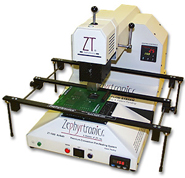
The
ZT-7 has
been on the market since 1998 and is still the
number one system on earth with a customer base as
sterling as it gets. The
ZT-7 is at
work as you read this webpage around the planet in
every field where PC board assembly work, rework,
repair or prototype design is done.
Zephyrtronics was ahead
of its time with the first single-spot, single-axis
BGA placement system, the first Z-axis and
retractable Y-prime movable heat zone, the first
with ultra-thin nozzles that don't disturb adjacent
components, the first with a truly modular BGA
system, the first with theta locking nozzles, the
first with countdown timing, the first BGA system
with ramping bottom-side preheat and more. We did it
first long ago and our customers from those days are
still using their gear today. Dependability and
quality!
There's no reason to risk throwing your company's
good money away and getting stuck on unproven, new
BGA "machines" that may not even be around next
year.
You
don't need to take a chance with your PCB work
when your bench can have the
ZT-7. The
same ZT-7 used by the most prestigious companies on
the planet, that has a proven history since 1998,
that is manufactured with quality and pride here in
the U.S.A., and that ships with a 2-year limited
warranty. |
|
|
|
|
|
|
|
|
|
|
|
|
|
|
| |
|
  How To:
 RE-DRESSING BGA & PADS WITHOUT SOLDERING IRONS & WICK
|
|
|
|
|
|
|
|
|
|
|
|
|
|
|
| |

STEP 1: BGA
removal requires cleanup as unequal
solder deposits will still remain at
vacated site. After chip removal, slide
the “Y” Axis of ZT-7 back out of way,
and apply flux to pads. Begin preheat to
the bottom of the PCB at 150°C with
the
AirBath™. |
|

STEP 2 (OPTION “A”):
After briefly preheating
(soaking) your PCB and generously
applying flux, use a heated
DeSoldering Tool with a “soft tip-pad
interface” and suck up excessive solder
from your pads. Preheating permits
lower, safer temps for all
DeSoldering tasks. |
|
|
|

"Vision Award" Awarded to Zephyrtronics in Recognition
of Its Breakthrough
"AirBath Device" for Preheating at the Benchtop |
|
The
Zephyrtronics AirBath is Featured in Ray Prasad's
Definitive Text
"Surface Mount Technology" |
|
"Innovative...simpler, safer way to
remove and repair sensitive devices" The Editorial
Staff, SMT MAGAZINE |
|
|
|
|
|
|
|
|
|
|
|
|
| |

STEP 2 (OPTION “B”):
A popular method is to
generously apply flux and
melt
LowMelt®
DeSolder into the residual solder on the pads
with the
AirBath™.
Remove all solder with a foam swab or Solder Sucker |
|
|

TM
STEP 3:
Switch off the ZT-7 and the
AirBath. Gently clean site with a foam
swab and a Non-Flammable Flux Remover.
Inspect. (Notice? No Wick!) |
|
|
|
|
|
|
|
|
|
|
|
|
|
|
|
|
|
| |
|
|
 |
|
|
|
|
|
|
|
|
| |
|
©1996 - 2011, 2012, 2013, 2014, 2015, 2016, 2017, 2018,2019,
2020, 2021- 2025 by Zephyrtronics®. All rights reserved.
The information, text, images, photographs, charts, graphs you
receive online from Zephyrtronics® are protected by the
copyright laws of the United States. The copyright laws prohibit
any copying, redistributing, retransmitting, or repurposing of
any copyright-protected material. Zephyrtronics is the
registered trademark property of JTI, Inc. "The Science of
Zephyrtronics" and "Simplicity Through Innovation" and "Zephlux"
and "ZeroLead" and "Zero Balling" and "Zero Residue" and "Post
Cooling" and "Post Cooler" and "AirBath" and
"SolderGlide" and "ZeroTouch" and "SolderMill"
and "Just So Superior" are the protected trademark
property of JTI, Inc. "Zephyrtronics" and "Low Melt" and "Air
Fountain" and "Fountainhead" are the registered trademark
properties of JTI Inc. *The above names are the registered
property of their respective owners. |
|
|
|
|
|
|
|
| |
|
| |
|
SMD Rework,
SMT Rework
AirBath Air Bath,
SMD Rework Stations,
Hot Air Pencil Soldering,
BGA Rework Stations,
CSP Rework Stations,
Preheating Systems,
PCB Preheaters,
Pre-Heat SMT/ SMD,
Low Temp Rework,
SMT DeSoldering Tools,
Vacuum Pickup Tools,
Circuit Board Holders,
PCB Fixture & PCB Holders
&,
Board Cradles,
Rework Solder Paste,
No-Clean Solder Paste,
Low Melt®
De-Solder Wire,
DeSolder Wire,
Hot Air Rework Stations,
Fume Extractors,
SMT Dental Probes,
SMT, SMD Rework Kit,
BGA Rework Kit,
LMK Kit,
BGA Re-Balling Kit,
SMD Tweezers,
Power Palm Plunger,
QFP Lead Straightener
How To - SMT,
CSP, BGA Rework
How To - BGA Alignment;
How To - SMT Rework;
How To - PCB Preheating,
How To - BGA & CSP Rework;
How To - Quickly Solder
SMD Packages Effectively;
How To - CSP Alignment;
How To - Lead-Free Rework;
How To - SMD Removal
Economical;
How To - SMD Removal
Professional;
How To - Hot Air Pencil /
AirPencil Soldering;
How To - SMD Quick Chip
Removal;
How To - BGA Re-Balling;
How To - Rework PLCC, QFP,
QFN, LCC, SOIC, SOL, Shielded SMD, TSOP;
How To - Solder & Rework
Ceramic Capacitors;
How To - Solder & Rework
Glass Diodes;
How to Repair Smartphones,
Tablets and Laptops
Soldering,
De-Soldering
Soldering Accessories,
Solder Wire,
No-Clean Solder Wire,
Eutectic Solder Wire,
Solder Wire Dispenser,
Solder Paste,
Lead-Free Solder Paste,
Flux,
Solder Paste Dispensers,
Low Melt®
DeSolder Wire,
De-Solder Wire,
Soldering Tips,
Thru-Hole DeSoldering
Tools,
DeSoldering Tips,
Tips for DeSoldering,
De-Solder Wick &
DeSoldering Braid,
Smoke Extractors,
Fume Extractor Filters,
Carbon Activated Filters,
SolderMill™,
Solder Sucker / DeSolder
Pump,
Pre-heating Systems,
Preheat Thru-Hole,
PCB Pre-heaters,
Flux Solvent,
How To - Connector Rework;
How To - PC/104 Soldering
and Rework;
How To - Thru-Hole /
Through Hole Desolder / De-Solder;
How To - Low Melt®
Desolder Wire;
How To- Stop Lifting Pads;
How To- Desolder /
De-Solder Heavy Ground Planes;
How To - Lead-Free
Soldering and De-Soldering;
Pre-Heaters for Lead-Free Rework and Soldering
Dispensing Equipment, Gear, Supplies, Dispensing
Bottles & Dispensing Accessories
Dispensing Systems,
Dispensing Syringes,
Dispensing Barrels,
Tapered Dispensing Tips,
Blunt Needles,
Dispensing Bottles,
Stainless Steel Needles,
Dispensing Needles,
Industrial Needles,
Dispensing Tips,
Industrial Dispensing
Tapered Tips and Needles,
Dispensing Accessories,
Flux Bottles,
Solder Paste in Syringe,
Paste Rack Solder Paste
Holder™,
Dispensing Supplies,
Power Palm Plunger,
Manual Dispensing,
Alcohol Pump Bottles,
Automatic Dispensing,
Squeeze Bottles, Wash
Bottles, Brush Bottles, Spout Bottles, Pump
Bottles
Benchtop Accessories,
Bench Supplies,
Benchtop Tools
SMD Solder Paste,
Solder Wire,
LowMelt®,
No-Clean Flux,
BGA Flux,
Rework Tack Flux,
Non-Flammable Flux Remover,
Pen Vac,
SMT Tweezers,
Fume Extraction,
SMD Tweezers,
PC Board Fixtures,
Hot Air Tips,
AirTips,
Replacement Soldering
Sponges,
Iron Plated Soldering Tips,
Foam Swabs,
Anti-Static Foam Swabs,
Thru-Hole & Solvent
Brushes,
Helping Hands,
LMK Rework Kits,
X-BOX 360 Repair,
Wire Strippers & Wire
Cutters,
Flush Cutters, Micro
Shears & Needle Nose Piers,
Straightening Tool for QFP
Leads,
ESD Wrist Straps,
ESD Wrist Strap Tester
Updated
for
March 25, 2025 |
|
|
|
| |
|